
Please view our website with a desk top or note book computer.
It is not written for a smart phone!
Email Reply's, Order Confirmation & Shipping Confirmation:
Check your spam folder!
Smart Phone only:
Click on the white square box with 3 horizontal lines below.
Shopping Cart payment system issues:
If your card is getting rejected it likely is the security on your card provided by your bank. To fix this: Use a different card or call your bank.

This page under construction All text in purple means it still needs test, confirm and edit
This page will not work on your smart phone. Use a PC!
These instructions are for our 2026 year model 20 amp mosfet controllers.
Most P- Settings are the same as our 2024 model.
They do not apply to the 2025 model. That is still in paper format and shipped with the controller
P 17 must be programed correctly. Since doing it wrong can damage your motor and or main board beyond repair: It is password protected.
All images and information found on this page is copyright protected.
Some Functions are Locked to protect It From Damaging or Unsafe Settings.
Should you hack or enter a provided password, You do so at your own risk. We will not be liable or responsible for your actions. It may also reduce or eliminate the warranty.
To set/program controller: Power up the controller display shows:
A. Press both & at the same time for 1 second to enter programing mode.
Display will light all 4 digits with the first digit flashing. It's asking for a dealer only access code.
Your controller is already programed to match the motor/kit it was shipped with.
Instead just press the The display will flash Nc and go strait to P - settings See below:
B. Use or Scroll up or down to the setting you wish to change.
C. Click to enter select correct P-__ setting for motor. See list below.
D. Use or Scroll up or down to the correct P -__ is displayed
See P - ____ Settings Chart Below.
E. When you have the P- # selected pres the button to enter that control.
F. Use or Scroll up or down to to the desired setting.
G. Press the button to save that setting.
Repeat/start at A for each P- ____ you wish to change.
These are the settings available With & Without an access code.
You should not need to change any of them anyway.
.P - 01. Set to 300. 200 to ~ This is the slow speed RPM limit. It is advisable to set at 500.
.P - 02. Set to . 1500W and 900W motors are 500 to 3500 RPM - 550W and 750W motors are 500 to 3500 RPM
.P - 03. 2 This is reverse on the fly Requires access code.
.P - 04. oFF. Do not change. Was previously used for external hall position sensors.
.P - 05. 0 Change if the red reverse light indicates on or off in relation to the direction of the motor. likely does not apply anymore.
.P - 06. 1 Soft Start and acceleration speed are one and the same. 1 is as soft as possible. Do not increase too much as it places load on belts etc.
.P - 07. 80 This is brightness of TACH display if equipped. 0 is off 99 is as bright as it goes..
.P - 08. 0 Motor braking. 0 is as soft as possible. Do not increase too much as it places load on belts etc.
.P - 09. . Access Code Set. If you forget what you changed it to: You have to pay to ship it to us for reset.
.P - 10. . 10. Position adjustment. Not used without additional sensors. Leave it alone.
.P - 11. oFF. On only locks P - 02 so that you cannot change top speed any more
.P - 12. . 50. Action time between external sensors. Not used. Leave as is.
.P - 13. 1. Synchronizer type.
.P - 14. 1. Not used.
.P - 15. 1. Speed display on. Note: Setting at 0 freezes display at 0. Setting at 3 freezes display at Top speed available.
.P - 16. oFF. Factory reset.
.P - 17. Because too many have done damage setting this wrong: This is preset to the motor you purchased. Unlocking it so you can run a brand X motor will increase the price + reduce the warranty.
.P - 18. . 45. Software version. 44 and 45 are reverse on the fly capable.
.P - 19. oFF. High speed Kp coefficient PID regulator. Off is default. On does nothing so far.
.P - 20. 0. 0 is default. The higher P-20 is set the longer initial acceleration is delayed.
.P - 21. 400. No use.
.P - 22. . . This is system speed limitation. Requires access code. We accept no liability should you change it. Overclock voids warranty
.P - 23. set to 1. Motor strength 1~3
.P - 24. No use.
.P - 25. set to . 10. Low speed Kp coefficient PID regulator.
P - 32 1 if 1 the potentiometer stops motor completely if 2 poteniometer slows motor to 200 rpm and the red button turns on/off
Notes:
1. Noisy likely means P-17 is set wrong and it's firing the fields at the wrong time.
2. Many motors have a physical limit as to how fast or how slow they will run: Programing them to run faster than the physical
limit will actually reduce top speed and performance. For this reason: If your motor tops out at say 3,900 RPM, set the top speed at no
higher than 4,000 RPM, This will actually improve top speed by as much as 50 RPM's
Accessories: 2026 version.
1. TACH Display Light: Brightness is from off to full. See P-7 and how to enter P-settings above.
The voltage on the 2 pins is 5 V DC. It will run small LED displays that run on 5 volts.
It will not run 12 V tach's.
Programing errors that cause functions not to operate:
No Reverse Function of Blue Button.
P-03 must be set to 2. See P - settings above.
Motor still runs at 200 RPM even with speed knob rotated to stop.
P-32 must be set to 1. See P - settings above.
Fault Codes 2026 version
__________________________________________________________________________________________
ER 1 Over voltage
Check input power voltage or replace main board. Usually resulting from a jam or shorting out speed switch.
ER 2 No Information
- - - - - - - -
ER 3 Over current
Check motor connector, or replace main board. Usually resulting from a jam or shorting out speed switch.
ER-3 Often was a burnt mosfet in the 2024 system with 15A mosfets. The 2026 controller has 20A mosfets.
See how to test it and replace mosfets: click here to watch 0ur YouTube Video
Note: Switching 15A mosfets to 20A mosfets will require all 6 as a matched set. Switching the software from 44 to 45
may or may not be an advantage. Further testing will reveal the truth.
Buy mosfets 15A here: OEM mosfets for 2023 and 2024 controllers
Buy 20A mosfets (set 6) pending.
ER 4 Rotary switch fault: Non existent in software Version 44 or 45 with potentiometer speed control.
ER 5 Synchronizer fault: Non existent in software Version 44 or 45 with reverse on the fly.
ER 6 Hall fault
Check motor connector, or replace motor. See repair of hall sensors needs confirmation still..
ER 7 Lock rotor fault
This is usually caused by binding and jamming. not in motor but in your machine. Check motor connector, or machine head.
PD Speed Switch
Turn speed to zero, make sure the red run switch is off (popped out) and wait 5 seconds. Cycle power if required.
Possible red run/stop switch.
Diagnostics V. Check speed switch and Motor Function for 2026 Version with Software version 45:
See Below pin out image below for 2026 model.
To enter readout function:
Press and hold down Turn power rocker switch on.
As soon as you hear a click, release the yellow button.
# A Speed control switch:
your display should look something like this: A0.00 That is the speed switch in stop position
Rotate it clockwise the numbers go up until you reach full speed A5.00 That is 5 volts.
Yes this displays the 0 to 5 V signal used to control motor speed.
Press to switch from A above to B below.
# B. Synchronizer not equipped, this is an external component.
Your display should show: 600 There is nothing to test here as your motor is not equipped.
Turn the wheel:
“U” will be displayed to show position 1
“D” will be displayed to show position 2
Press to switch from B above to C below.
C. Hall Sensors in Motor. (Fault Code 6)
Rotate motor to display hall value:
Display will read C 1 through C 6 as you rotate by hand.
Fault state, If you get an “E” in any position:
That hall sensor is defective. The general thought here is
the motor needs to be replaced?
We have hall sensors.
This job is very difficult to perform successfully. That is why most just say replace the motor.
However if recent events have you wanting to fix it for as little as possible. See links below:
550W, 750W and 900W use these: Hall sensor set small motor
1,500W These should be easier: Hall sensor set 1500W motor
1: 750W with 4,000 rpm limit
2: 8-pole 550W motor (see 6 pole below)
3: 6-pole 82mm diameter 400W motor.
4: 600W & 800W motor.
5: Unknown
6: Our 1,000W & 1,500W motors.
7. Unknown
8. Our 6-pole 550W motor + 500W 76mm
9. Our 6-pole high performance 750W
Includes 650W 76mm motor.
10. Unknown.
11. To be announced.
12. Our High torque 6-pole 900W 76mm
motor.
13. Do not use may cause damage
14. Do not use. May cause Damage.
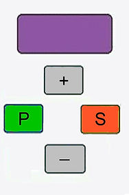
Diagnostics V. Check speed switch and Motor Function for 2024 Model:
The below info is not for the inexperienced.
To enter readout function:
Turn everything off and wait 60 seconds. This allows all capacitors to drain.
Press and hold down Turn power rocker switch on.
As soon as you hear a click, release the orange S button.
Your display should look something like this: That is the speed switch # A in stop position.
It reads out the voltage 0 to 5 volts as you turn the speed pot clockwise the voltage increases to
volt when at full speed clockwise to right it reads:
# A Speed control switch:
Slowly rotate from stop to full, displays: A000 increases to A500 as you rotate the speed knob or close to it.
Voltage is what is shown on the last 3 digits. Ignore the first symbol.
---------------------------------------------------------------------------------------------------------------------------------------
Press P to switch from A and to B read out below.
B. Synchronizer not equipped, this is an external component.
Display will show: 611
Motor is not equipped with external hall position sensors.
There is nothing to do here.
----------------------------------------------------------------------------------------------------------------------------------------
Press P to switch from B and to C read out below.
C. Hall Sensors in Motor. (Fault Code 6)
Rotate motor to display hall value:
Display will read C 1 through C 6 as you rotate by hand.
Fault state, If you get an “E” in any position:
That hall sensor is defective. The general thought here is
the motor needs to be replaced?
We have hall sensors.
This job is very difficult to perform successfully. That is why most just say replace the motor.
However if recent events have you wanting to fix it for as little as possible. See links below:
550W, 750W and 900W use these: Hall sensor set small motor
1,500W These should be easier: Hall sensor set 1500W motor